
Drainage Act Report: Southdown Drain
Prepared By: Credit Valley Conservation (CVC) and K. Smart Associates Ltd.
December 2023
Executive Summary
This report provides an example application of the Drainage Act, R.S.O. 1990 (Drainage Act) for creation of a communal stormwater system using low impact development components retrofitted on private properties in an existing 37.4 hectare industrial/commercial catchment in Mississauga’s Southdown District. The study area is bounded by Royal Windsor Drive to the southeast, Southdown Road to the northeast and the CN railroad to the northwest.
If petitions for drainage works by owners were filed with the City of Mississauga, council could appoint an engineer under Section 8 of the Drainage Act to prepare a report to address the petitions received. At the time of writing, there are no landowner petitions and no council appointment for drainage works in the study area, thus this report is not an authoritative report under the Drainage Act.
However, in the manner of a typical Drainage Act report, this document provides background information, design criteria, public consultation, agency considerations, alternatives reviewed, recommended work, cost estimates and assessment schedules for cost-sharing of the initial construction and long-term maintenance of the system among the affected lands and roads.
Highlights:
The watershed includes thirteen private properties, the CNR corridor and Royal Windsor Drive.
The following scenarios were investigated for the 37.4-hectare study area:
- Scenario 1: Existing conditions, the current condition of the study area as an industrial commercial neighbourhood.
- Scenario 2: Communal LID retrofit design that maximizes the City of Mississauga’s stormwater credit. The design of communal LID retrofits under this scenario is based on meeting the minimum level of service, at the lowest cost for private property owners to be eligible for the total allowable rebate (stormwater credit) on the stormwater utility fee in the City of Mississauga.
- Scenario 3: Communal LID retrofit design that maximizes “one water” opportunities and system co-benefits. It builds on scenario 2 as this scenario provides the level of service that surpasses what is required for the total allowable rebate on Mississauga’s stormwater utility fee. It includes further optimizing the design for co-benefits of LID and considers other municipal water systems (i.e. reducing sanitary inflows and potable water use through reuse).
- Scenario 4: A conventional centralized end-of-pipe conceptual design on public property.
The recommended drainage scheme per scenario 2 serves 16.4 hectares and consists of branches D through I, which each outlet to the city’s storm sewer along Royal Windsor Drive, as shown on drawing 1 in Appendix D.
The estimated cost of the initial construction of scenario 2 is $4,925,860. Including operation and maintenance costs, the total 50-year life-cycle cost of scenario 2 is $5,342,860.
Contents
- Background
- Investigation
- Authority for Report
- Approvals
- Design Considerations
- Cost Estimate
- Results, Discussion and Recommendations
- Assessing Drain Cost
- Maintenance
- Report Limitations
- Privacy of Lands
- Bylaw
- References
- Publication Information
- STEP
- Acknowledgements
- Notice
1 Background
1.1 Appointment
A petition for drainage worksunder section 4 is a legal document that initiates the Drainage Act process.
- A petition can include the signature(s) representing only a single property.
- A petition can include the signature(s) representing multiple properties.
- Multiple petitions representing multiple properties can be addressed under a single report.
- A petition can be signed by a road authority.
- A petition can be signed by the director of OMAFRA.
Once a petition is filed with the municipality, council appoints an engineer by by-law or resolution to prepare a report on the petition.
For each petition that is filed, the engineer must arrange an on-site meeting with landowners to determine the area requiring drainage and confirm the validity of the petition under section 9(2). For each area requiring drainage, the engineer is authorized to design a drainage works.
This report assumes petition(s) representing the entire study area were filed by landowners and council appointed K. Smart Associates to prepare a report on the petitions received. Refer to section 4 of this report for further discussion on the relationship between petitions filed and the extent of the drainage works authorized by those petitions.
1.2 Study Area Location
The study area shown in Figure 1 is comprised of 37.4 hectares of largely employment lands, consisting of 13 individual property parcels bounded by Royal Windsor Drive to the southeast, Southdown Road to the northeast and CN railroad to the northwest.
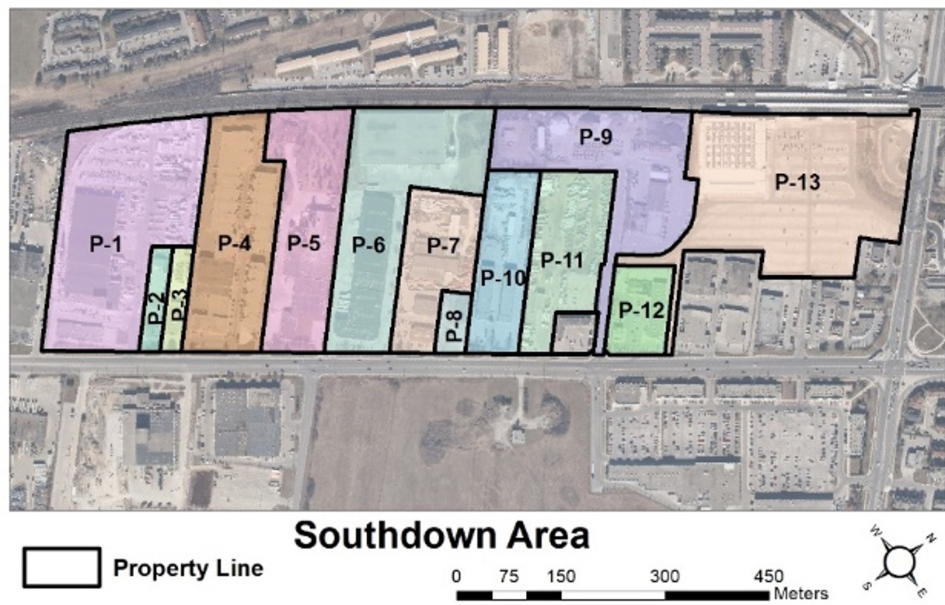
Figure 1. Properties in the study area. Royal Windsor drive is the study area’s southeastern boundary at the bottom of the figure. Abbreviation: P, property.
1.3 Other Reports and Studies
The following studies and reports were referenced during preparation of this document or are relevant to implementation of recommendations provided by this document.
- Aggregation Methodology for Communal Stormwater Management Retrofits on Private Property, CVC, 2023.
- Technical Peer Review – Scenario 4 (End of Pipe option for Study Area), Wood, 2021
- Priority Tree Planting Areas to Grow Peel’s Urban Forest, Beacon Environmental Limited, 2015.
- Peel Tree Planting Priority Tool, Beacon Environmental Limited, 2015.
- Infiltration and Inflow Reduction and Mitigation Strategy, Stantec, 2018.
- City of Mississauga Stormwater Master Plan (ongoing)
- Low Impact Development Life Cycle Costing Tool, TRCA, 2021. [1]
2 Investigation
2.1 Initial On-Site Meeting
The first step of the investigation process, described in section 9 of the Drainage Act, is an on-site meeting between the engineer and landowners to gather background information, understand drainage objectives and review site conditions.
Six of the fourteen properties in the study area attended an on-site meeting on May 14, 2018 along with staff from Credit Valley Conservation Authority (CVC), City of Mississauga, Region of Peel and K. Smart Associates Limited.
The meeting began with a brief presentation to landowners about the Drainage Act process, the role of LIDs in stormwater management and the purpose of the on-going CVC feasibility study. Landowners were informed no formal Drainage Act petitions have been submitted to date.
The following summarizes comments from landowners in attendance:
Property 1 (2 representatives)
- Expressed interest in bioswales and underground runoff storage near rear of property.
- Rooftop storage could also be an option as they could make use of the stored volume.
Property 2 (1 representative)
- Property has drainage issues during storms, would like to have drainage problems addressed but mindful of potential costs.
- Concerned about basement flooding due to poor infiltration.
- Interested in rooftop storage on buildings in rear of lot.
- Would also make use rooftop storage from neighbours, unsure of financial implications of such an arrangement.
Property 3 (1 representative)
- Invested about $60,000 in a private storm system after purchasing property to resolve drainage issues.
- Believes a bioswale could work near front of property.
- Rear of property is currently gravel, interested in permeable paving.
- Interested in reducing water bill by re-use of stored water for irrigation.
Property 4 (not present)
Property 5 (2 representatives)
- Very interested in LID methods but concerned about costs/payback period.
- Structural concerns would limit rooftop storage options for now.
- Interested in bioswales near fence because that portion of property is not used, but concerned about bioswale maintenance, especially as it affects security. Ready access to their fence is needed for inspections to ensure security/safety of property.
- Interested subsurface storage and permeable pavement for employee parking lot.
- Not in favour of a constructed wetland due to concerns about permanent pool.
Property 6 (not present)
Property 7 (2 representatives)
- Has drainage problems on property.
- Would like to cleanout swale at back of property.
- Curious about permeable pavement performance, too hot in summer or too slippery during winter. Would like a cost comparison vs. standard asphalt repaving.
- Believes the shared driveway to the east would be a good retrofit location.
- One of their tenants produces excess wood chips that may be available for use on this project.
Properties 8, 9, 10 and 11(not present)
Property 12 (2 representatives)
- Interested in installing features with an environmental benefit.
- Would like to engage day care kids in the project in some way.
- Interested in bioretention, green roof options and permeable pavement—as long as lines can be painted on the pavers. Concerned if pavers would be slippery.
Overall, there was a high level of interest in LID approaches among the landowners who attended and use of the Drainage Act framework to construct and maintain the drainage systems. Near the end of the meeting, CVC and K. Smart staff informed landowners that a topographic survey would occur on each of their properties to facilitate the design process.
2.2 Site Review and Survey
Spatial analysis by CVC determined approximately 70 per cent of the study area is impervious (pavement and building), 10 per cent is gravel parking/storage areas, and the remaining 20 per cent comprises lawn and vegetated areas.
A topographic survey of all 13 properties was completed between July and September 2018 with nearly 7,000 points surveyed. Information included water main, sanitary and stormwater networks, other buried utilities marked by Ontario One Call, catch basin inlets, maintenance hole locations and grass swales. Where accessible, the following information was also collected; pipe diameter, slope, length and invert/obvert elevation.
As a fully developed urban watershed, drainage patterns are a function of subsurface piping and surface features like swales, lot grading and curbs. The northwestern boundary of the study area watershed is within the CNR corridor, with the southeast portion of the corridor draining into the study area in multiple locations. The general drainage pattern across the study area is southeasterly, with multiple outlet connections into the city’s storm sewer under Royal Windsor Drive. The storm sewer along Royal Windsor Drive flows north easterly to Sheridan Creek (see Figure 2).
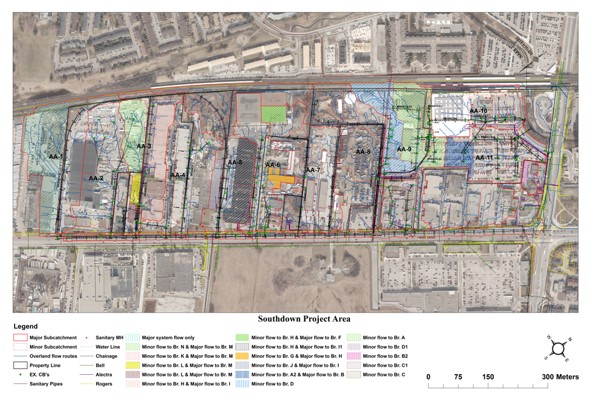
Figure 2. Major and minor system boundaries for the study area.
2.3 Subcatchment Delineation
The study area’s hydrology and hydraulics is represented by subcatchments for the major and minor system. The major and minor subcatchments are not always the same; in some cases, the two systems have different boundaries (see Figure 3 and Figure 4).
Minor system flows are all directed through the municipal storm sewer along Royal Windsor Drive to the south eastern boundary of the study area to Sheridan Creek. The major system flows spill into the Avonhead Creek (western), Lakeside Creek (central), and Sheridan Creek (eastern) Watersheds.
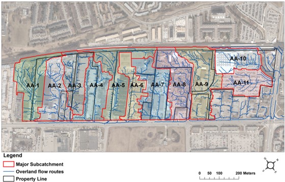
Figure 3. Major system subcatchments AA-1 to AA-11 in the study area.
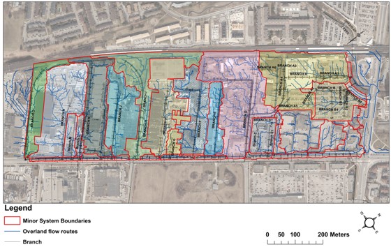
Figure 4. Minor system boundaries for the study area, with branch drains labelled.
To identify major system subcatchments, the nomenclature “AA-1”, “AA-2”, etc., was applied.
To identify minor system components, the existing municipal storm sewer along Royal Windsor Drive was labelled as the main drain and the private drainage systems (pipes, catchbasins, and swales) that tie into the main drain were referred to as branch drains. Each branch drain (or “branch”) is then labelled (“ranch A”, “branch B”, etc.), measured, and assigned station numbers. Figure 4 shows branches A to O.
The drawings in Appendix D provide plans, profiles and details for each branch and sub-branch of the proposed drainage works under design scenarios 2 and 3.
2.4 Soil Permeability Testing
Hydraulic conductivity testing using the Guelph Permeameter was completed at nine separate locations across the Southdown study area. Results show the study is generally suitable for infiltration-oriented LID features. The mean and median estimated infiltration rate was 51 millimetre per hour and 50 millimetre per hour, respectively. The project team used a conservative design approach and applied an infiltration rate of 2.5 millimetre per hour for design and modelling. Details of the soil permeability testing and results are provided in Communal Low Impact Development Approaches to Manage Stormwater (CVC, 2022).
2.5 Natural Heritage Features
There are minimal natural heritage features in the study area. Of the entire 37.4 hectare study area, scattered lawn and incidental vegetated/wooded areas cover approximately 7.4 hectares. There are no environmentally sensitive natural watercourses, riparian corridors, wetlands or coastlines in the study area.
3 Authority for Report
As mentioned in section 2.1, this report assumes petition(s) representing the entire study area were filed by the landowners and council appointed K. Smart Associates to prepare a report on the petitions received.
If only a handful of landowners in the study area filed petitions, discrete portions of the system recommended in this report could be implemented to serve the petitioning properties. This is because each petition gives rise to an area requiring drainage, which is determined by the engineer and for which a drainage scheme can be designed.
Table 1 below illustrates which property owner signatures are required to meet the section 4 thresholds for the area requiring drainage. If section 4 thresholds are not satisfied, additional signatures are required to authorize construction of the drain.
Table 1. Property owner signatures required by section 4 criteria.
| Scenario 2 Component | Petitioning landowner(s) required to satisfy Section 4 criteria re. Area Requiring Drainage |
| Branch A | P-13 |
| A1 | P-13 |
| A2 | P-13 |
| A3 | P-13 required CNR optional |
| A4 | P-9, P-13 |
| A5 | P-13 |
| A6 | P-9 |
| Branch B | P-13 |
| B1 | P-13 |
| B2 | P-13 |
| B3 | P-13 |
| B4 | P-13 |
| Branch C | P-12 |
| C1 | P-12 |
| Branch D | P-11 required P-9 required for work upstream of 0+270 P-13 optional |
| D1 | P-12 and P-13 |
| D2 | P-9 |
| D3 | P-11 |
| Branch E | P-10, P-11 |
| Branch F | P-7 and P-10 up to 0+243 P-7 and P-6 for work upstream of 0+243 P-8 optional |
| F1 | P-6, P-10 |
| Branch G | P-7 |
| Branch H | P-6 and P-7 |
| Branch I | P-5 and P-6 |
| I1 | P-6 |
| I2 | P-5 CNR optional |
| Branch J | P-4 and P5 |
| Branch K | P-4 CNR optional |
| Branch L | P-3 and P-4 |
| Branch M | P-2 and P-3 |
| Branch N | P-1 |
| fN1 | P-1 |
| N2 | P-1 |
| N3 | P-1 |
| Branch O | P-1 |
4 Approvals
4.1 Environmental Agency Approvals
Agency approvals are typically obtained before a report under the Drainage Act is filed. Typical agency submissions include: MECP where species at risk considerations apply, Fisheries and Oceans Canada where fish and/or fish habitat impacts are anticipated and the conservation authority.
Considering the fully-developed nature of the study area, species at risk concerns are not anticipated and proposed work locations do not impact fish or fish habitat. A copy of the preliminary drawings were forwarded to Credit Valley Conservation Authority for review and their comments have been incorporated in the proposed work.
4.2 Municipal Approvals
As a project under the Drainage Act, construction of the proposed drainage works requires adoption of this report via municipal by-law.
In lieu of the standard site plan application process, before the report is filed, preliminary drawings should be circulated to the applicable road authorities to ensure compliance with municipal requirements for infrastructure in the public right-of-way.
Since the funding mechanism for the proposed work involves Drainage Act assessments and credits from the municipal stormwater utility, those portions of the work, for which stormwater credits are anticipated, were reviewed with municipal staff to ensure eligibility.
Construction-related authorizations such as permits for working in road allowances, traffic plans, etc. will be obtained once a contractor is identified. Although the drainage works consists of multiple sub-systems (branches), each having separate tie-ins to the city storm sewer, it will likely be more efficient from a permitting and cost standpoint for all of the work to be completed by the same contractor.
5 Design Considerations
5.1 Scenario Descriptions
To compare communal green infrastructure retrofits on private property against traditional stormwater management on public property, various scenarios were developed and modelled using an integrated 1D-2D PCSWMM model. The scenarios are:
- Scenario 1 – Existing Conditions: This scenario represents current condition of the study area.
- Scenario 2 – Maximum Credit: This scenario modelled communal LID designs that maximize available stormwater credit. This scenario uses the lowest-cost LID designs that qualify private property owners for the maximum possible credit (50 per cent) on their stormwater utility fee from the City of Mississauga.
- Scenario 3 – One Water: This scenario modelled communal LID designs that maximize available stormwater credit and also includes additional features that provide co-benefits for other water-related infrastructure systems (e.g., water reuse, tree planting, inflow and infiltration reduction, etc.).
- Scenario 4 – End of Pipe: This scenario modelled the conceptual design for a traditional, centralized end-of-pipe stormwater management facility.
Pre-development conditions of the study area were also modelled to compare the scenarios above with the study area in its pre-development, rural condition.
The scenarios will be examined in terms of their cost and level of performance. A number of environmental, economic and social benefits will be compared in order to select a preferred scenario.
As an urban study area, drainage is provided by sub-components for local conveyance, major flow conveyance and LID function.
Local conveyance systems and LID features generally shared the same upstream contributing watershed. Assessments for local conveyance improvements are generally to the abutting properties, whereas assessment for LID features and major systems are generally to downstream lands.
For each scenario, the contributing watersheds, construction costs, allowances and assessments were computed separately for each of the three sub-components using factors and ratios provided in the associated section of this report.
5.2 Sufficient Outlet
Section 15 of the act requires that the proposed work be continued downstream to a sufficient outlet. Section 1 of the act defines a sufficient outlet as “a point at which water can be discharged safely so that it will do no damage to lands or roads.” Since this project’s design reduces the flow to downstream lands, the existing storm sewers on Royal Windsor Drive would be a sufficient outlet.
5.3 Design Criteria
For each scenario, the following table summarizes the City of Mississauga’s stormwater credit criteria and the additional co-benefits that each scenario aims to provide.
Table 2. City of Mississauga stormwater credit criteria and additional co-benefits that each scenario aims to provide.
| Criteria | Scenario 1 (Existing Conditions | Scenario 2 (Max Credit) | Scenario 3 (One Water) | Scenario 4 (End-of-Pipe) |
| Return period storm | N/A | 100 yr | 100 yr | 100 yr |
| Peak flow reduction | N/A | Pre-Post development | Pre-Post development | Pre-Post development |
| TSS removal | N/A | Yes (80%) | Yes (80%) | Yes (80%) |
| Capture of first 15 millimetres of rainfall | No | Yes | Yes | No |
| Pollution prevention plan | No | Yes | Yes | No |
| Inflow and infiltration reduction | No | No | Yes | No |
| Tree cover | No | No | Yes | No |
| Reduce heat island | No | No | Yes | No |
| Reuse of water | No | No | Yes | No |
| Water conservation | No | No | Yes | No |
| Thermal regulation of outflow waters | No | Yes | Yes | No |
5.4 Location Considerations
Adequate working space is required along the route of the drain for future maintenance.
Where topography requires the drain to cross private lands, proposed routing is generally adjacent to property lines, to minimize property impact and to make use of land that is already subject to zoning setbacks. In these cases, section 29 allowances for right-of-way provided compensation to the landowner (See Section 7.2.1).
5.5 Utilities
Available public utility information was received from the city and is included in the drawings (Appendix D). During detailed design, Ontario One Call should be notified and private landowners consulted regarding the location of private underground infrastructure that may affect construction of the drainage works. The cost to relocate private services on private property will be included in the overall drain cost and assessed accordingly. Increased project costs due to public utilities will be assessed to the public utility under section 26 of the Drainage Act or paid for according to the terms of the applicable franchise agreement (if any).
6 Cost Estimate
6.1 Allowances
Sections 29 to 33 of the Drainage Act provides for allowances (compensation) to owners affected by the proposed drain. Allowances are paid only once when drainage works are established by an engineer’s report and the allowance amounts. Sections 29 to 33 cover the following allowances:
- Section 29 – Land and right-of-way
- Section 30 – Damages
- Section 31 – Existing drains
- Section 32 – Insufficient outlet
- Section 33 – Loss of access
Since allowances form a portion of the total project costs they must be realistic: a key consideration when assigning allowances is balancing what is fair to the property owner receiving the allowance with what is fair to those who are paying it. In other words, allowances should not be used to buy landowner support. Rather, they should compensate landowners for real effects to their property.
To compare how allowances may be provided under the Drainage Act in the rural and urban contexts, please see Table 3.
Table 3. Allowance comparison in rural and urban applicants.
| Allowance Category | Rural Application | Urban Application |
| Land and right-of-way | Land permanently out of production for construction of drain or for disposal of material removed from drainage worksLand as a site pumping station or access to site pumping stationRight-of-way periodically used for maintenance | Land permanently out of use for construction of drainRight-of-way property access for periodic inspection and maintenance/ rehabilitation |
| Damages | Ornamental trees, lawns, fences, lands and crops caused by the disposal of material | Property damages during construction, maintenance and rehabilitationBusiness disruption during construction and maintenance |
| Existing drains | Private drainage system | Private drainage system (pipes, catchbasins, manholes, swales, LID)Existing natural assets |
| Insufficient outlet | For not bringing drain to a sufficient outlet | Not anticipated for urban land uses |
| Loss of access | For not providing access to a section of property | Not anticipated for urban land uses |
There are a lot of similarities between allowances in rural areas and what is recommended herein for urban areas. In rural areas a land allowance may be given when a parcel of land is taken out of productivity; this applies similarly in an urban area where the use of the land has been compromised due to the presence of a drain. In urban areas it may also be warranted to provide an allowance for periodic property access to maintain the drainage works.
Traditionally damages under the Drainage Act process are due to the disposal of material during construction and maintenance. For urban land uses we do not suggest giving an upfront allowance for unrepaired damages, we suggest that any damages are repaired, and the costs be levied as per construction and maintenance assessment schedules in the engineer’s report. However, in urban areas there may be reason to provide a damage allowance for loss of income due to business disruptions.
Existing drain allowances are similar for private drainage works in rural and urban areas. Furthermore, in urban areas there may be value to incorporating existing natural assets (trees, pocket wetlands, etc.) as a part of the drainage works due to the stormwater and other benefits they provide.
In the urban context, we do not foresee a need for insufficient outlet or loss of access allowances and will provide the rationale in this chapter.
This section focuses on describing how allowances can be calculated for urban drainage works constructed under the Drainage Act. A more detailed description of each type of allowance that could apply in an urban context outlined in the following sections and summarized above is provided in this chapter, as well as methods for quantification.
6.1.1 Allowances for Land and Right-of-Way (Section 29)
Communal stormwater works are surface and sub-surface stormwater facilities that are located on private and/or public property. Land allowances provide compensation to the private property owner for the portion of land used for stormwater management and any buffer areas for right-of-way access.
The Drainage Act allows municipalities to secure an easement over privately-owned property in order to construct and maintain drainage works. Because easements secured under the act are “substantially equivalent” to expropriating the land for public purposes, landowners must be compensated accordingly (Rhodes v Raleigh (Township), 1898 ONDR 1).
To secure green infrastructure on private property under an easement, the drainage engineer needs to assign land and right-of-way allowances. If the land in question is to be under an easement, some allowance – even a token allowance – is required, or else the land’s status could be subject to dispute. For example, a bioretention median in a parking lot may displace parking stalls, a vegetated buffer may take up space that could otherwise be used for outdoor storage, or subsurface features may preclude future development (see Figure 5 to Figure 8 for examples).
Allowances for land can be full market value or partial market value for the permanent and/or periodic use of land and should be based on vacant land values in urban areas. Municipal Property Assessment Corporation (MPAC) values are conventionally used under the Drainage Act as a basis for determining unit land value for these types of allowances. This is a reasonable approach in rural Ontario where the land is predominately vacant however, in urban areas the MPAC values are not representative of vacant land due to development and the presence of buildings. As a result, land values in urban areas may be based on alternatives such as MPAC values for vacant land if available from the local municipality, the market value from recent sales of vacant land that is nearby, or by hiring a professional land appraiser. This section describes approaches and considerations for assigning land and right of way allowances for urban areas.
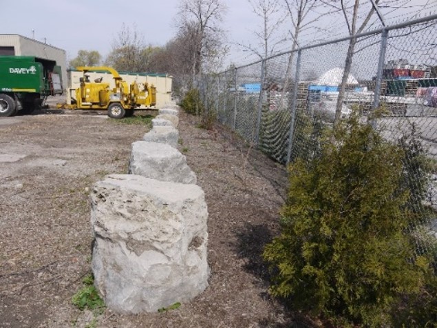
Figure 5. Land acquired for a vegetated buffer with stone barrier.
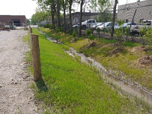
Figure 6. Swale along periphery of property.
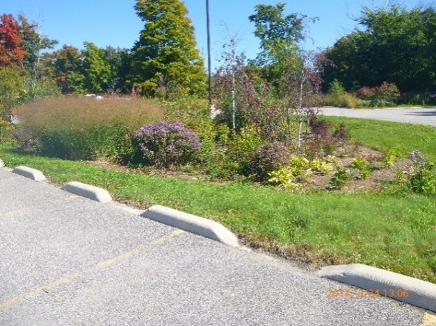
Figure 7. Example of where bioretention retrofit replaced parking stalls.
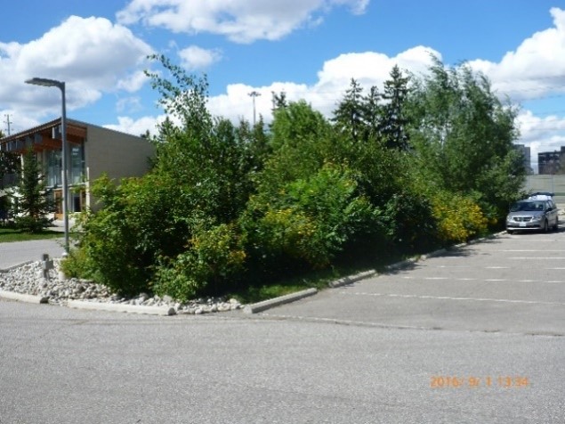
Figure 8. Example of where bioretention retrofit replaced parking stalls.
6.1.1.1 Allowances for permanent land use– full market value
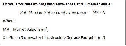
Full market value should be used for an area of land converted for surface stormwater management in scenarios where the LID practice precludes the use of the land for any other purpose and severely impairs the usability of the land. It is very rare to give full market for land and the engineer should attempt to locate the drainage works in a way to minimizes impairment to existing and future land uses and assign a partial market value. One approach to calculating this type of allowance is to use the surface area of the facility and any buffer areas and the market value of the property. The below formula provides an approach to calculating full market value allowances.
6.1.1.2 Allowances for permanent land use – partial market value
Often there are reasons to give a landowner partial market value for a parcel of land as many LID features can be implemented in periphery areas or in areas where the LID retrofit minimally impacts land usability. Location is a crucial design consideration when designing stormwater features on private property.
Pre-existing drainage features, gardens, lawns, parking islands and parking lots can be retrofitted with LID technologies with little to no loss in the function of the land. For example, if an existing swale is already in use for conveying stormwater, retrofitting with bioretention and bringing that land under an easement does not change the landowner’s use of it. In this case once the bioretention facility is secured under an easement, the landowner could not develop it or otherwise change its use, thus partial value should be given for the land. Another example is a sub-surface drainage feature such as an infiltration chamber or trench which can underly a parking lot or driveway without impeding use of these surfaces. While sub-surface infiltration chambers can accommodate most loads, they cannot bear the weight of large buildings or heavy supplies therefore the location of sub-subsurface facilities on the property may preclude future development therefore a partial market value allowance may be appropriate. Figure 9 to Figure 12 show examples where existing areas can be retrofitted with LID with minimal changes to land functionality.
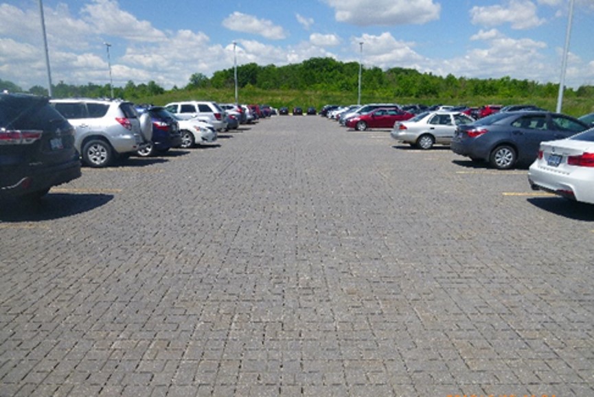
Figure 9. A parking lot retrofitted with permeable pavement still functions as a parking lot.
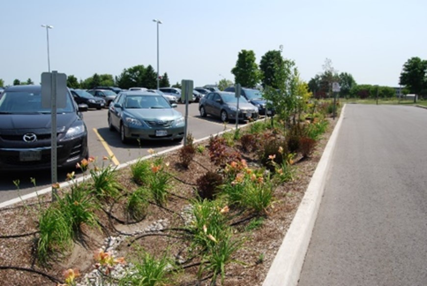
Figure 10. An existing grass parking median retrofitted with a bioretention swale causing no loss in land function.
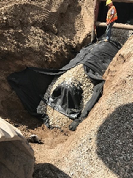
Figure 11. Infiltration chambers being placed under ground allowing the above ground surface to be available for use.
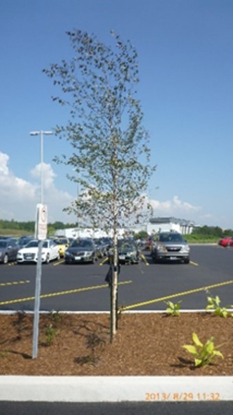
Figure 12. A bioretention facility in a parking lot that does not affect the available parking area.
LID and other stormwater features located along property lines or at the rear of properties are other examples where partial market value for land use would be warranted. Areas that have redevelopment restrictions or are in regulated area could see a further reduction in partial market value for allowances.
Once land is secured under an easement, it would preclude future land use changes. LID designs should aim to locate stormwater features outside of any areas where expansion or future development is planned.
Some proportion of land value should be the basis of the land value allowances based on the considerations described above. A formula that can be used to assign partial market value land allowances is provided below.
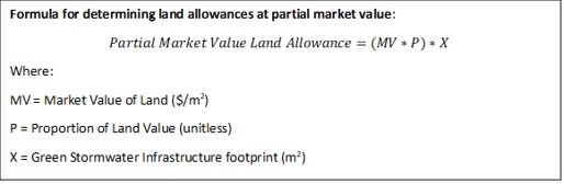
Table 4 summarizes criteria to consider and possible corresponding land value proportions that could be used to compensate landowners for locating green infrastructure on private property. If multiple land value criteria are desired, they may be weighted to determine a single factor for determining an appropriate proportion of full market value for land allowances.
Table 4. Criteria to consider for assigning partial market value for land.
| Land Value Criteria | Location of LID | Suggested Proportions |
| Above or below grade | Above grade | 1 |
| Below | 0.3 | |
| Location of feature on property | Center of property | 1 |
| Between center of property and periphery | 0.5 | |
| Periphery of property | 0.2 | |
| Land use conversion for SWM | Converting land for SWM that precludes future use of land | 1 |
| Converting land, but land can be used in the same way | 0.5 | |
| Pre-existing land already for SWM becomes part of the drainage works | 0.1 |
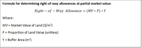
6.1.1.3 Allowances for periodic land use (right-of-way) – partial market value
Periodic land access is required to complete routine inspection and maintenance/rehabilitation activities. An allowance may be provided for the periodic use of land as an access way or working space when maintenance is completed. This allowance may be especially applicable for communal systems when drainage systems may be concentrated on a single property where maintenance frequently occurs compared to other properties that contribute runoff to the drainage works. A small proportion of the market value of land should be used for this type of allowance since right-of-way allowances are only for periodic use of a buffer area. This type of allowance can be calculated using the following formula.
6.1.2 Allowances for Damages (Section 30)
6.1.2.1 Damages Due to Construction
During any drainage project, a working area is defined and it is generally within that area that damages are expected during the construction process. One can expect trees, lawns, fences and asphalt in the working area to be damaged. Additional damages may occur outside the working area for access, clearing and new or reworked connections required as a result of construction (OMAFRA, pg. 54, 2018) and these should also be accounted for. If all damages are repaired as part of construction (recommended), then these costs would be included in the construction costs section rather than as an allowance for damages. This would generally be the case in an urban context as damages after an LID installation would not be left unremedied. In the case where damages are left unrepaired then an allowance would be required and in such a case the following formula could be used to assign an allowance.
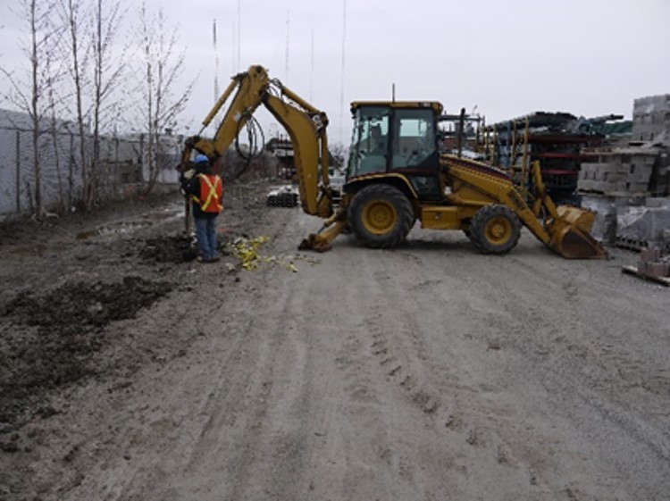
Figure 13. Equipment access during construction.
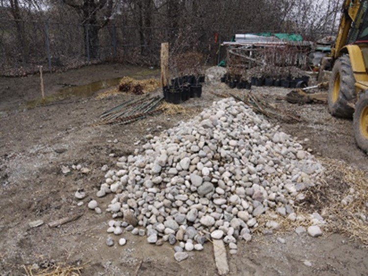
Figure 14. Temporary material storage during construction.
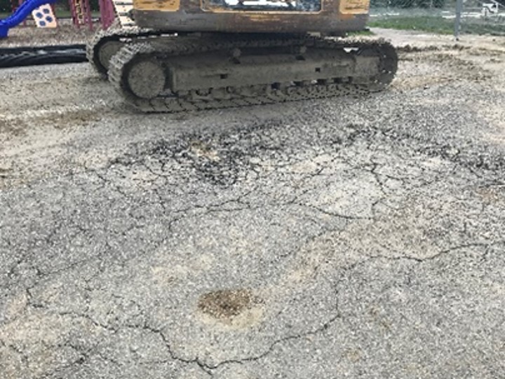
Figure 15. Damaged asphalt after construction of a bioretention facility was not a foreseen result of construction.
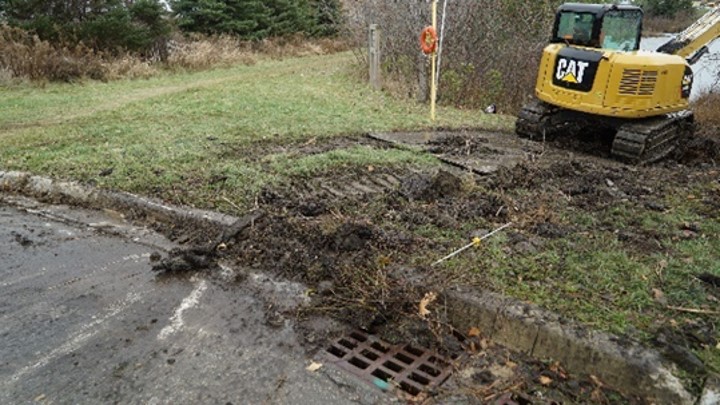
Figure 16. The cost to repair this foreseen damage to lawn and vegetation from an LID project in Brampton was included in the project tender.
6.1.2.2 Damages Due to Maintenance and Rehabilitation
Many LID facilities require periodic maintenance or rehabilitation throughout their lifetime. In urban areas it is suspected that the established network of roads and parking lots will be used to access the drainage works for maintenance and rehabilitation therefore if any damages occurred, they would be minor. Generally, damage is minimal during maintenance but may be more significant during rehabilitation. Damages for maintenance and rehabilitation can be addressed using two approaches:
- Leave future maintenance/rehabilitation damages un-repaired and compensate landowner with one-time allowance upfront at the time the drainage works is built, or
- Repair any damages during maintenance and rehabilitation with the cost levied out to landowners according to the proportions in the maintenance assessment schedule.
A disadvantage of addressing damages upfront as an allowance is that it is difficult to forecast the cost of future damages. It is also unadvisable to leave urban land in a state of disrepair after maintenance and rehabilitation. Therefore, it is suggested that when any needed repairs are completed, the costs be distributed at the time of maintenance as per the maintenance assessment schedules and directions provided in the engineer’s report (described in section 9.7 of this guidance document).
If there was a scenario where the engineer desired estimating maintenance and rehabilitation costs and providing an allowance for damages upfront it could be based on the planned frequency of maintenance and rehabilitation activities for the drainage works and the estimated value of future damages. The present-day investment needed to cover future damages can be calculated using the following equation (Guide for Engineers, pg. 52). The below example assumes that a drainage works needs rehabilitation in year 25 and year 50 of its life cycle, and that the damages associated with this have a future value cost of $2,500 each. This formula should be used for maintenance and rehabilitation separately as the frequency and future value of routine maintenance is different than that of rehabilitation.
It should also be noted that if rehabilitation work is significant and was not covered in the original engineer’s report, a new engineers report may be warranted to cover the work and the assessment of costs.
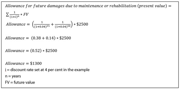
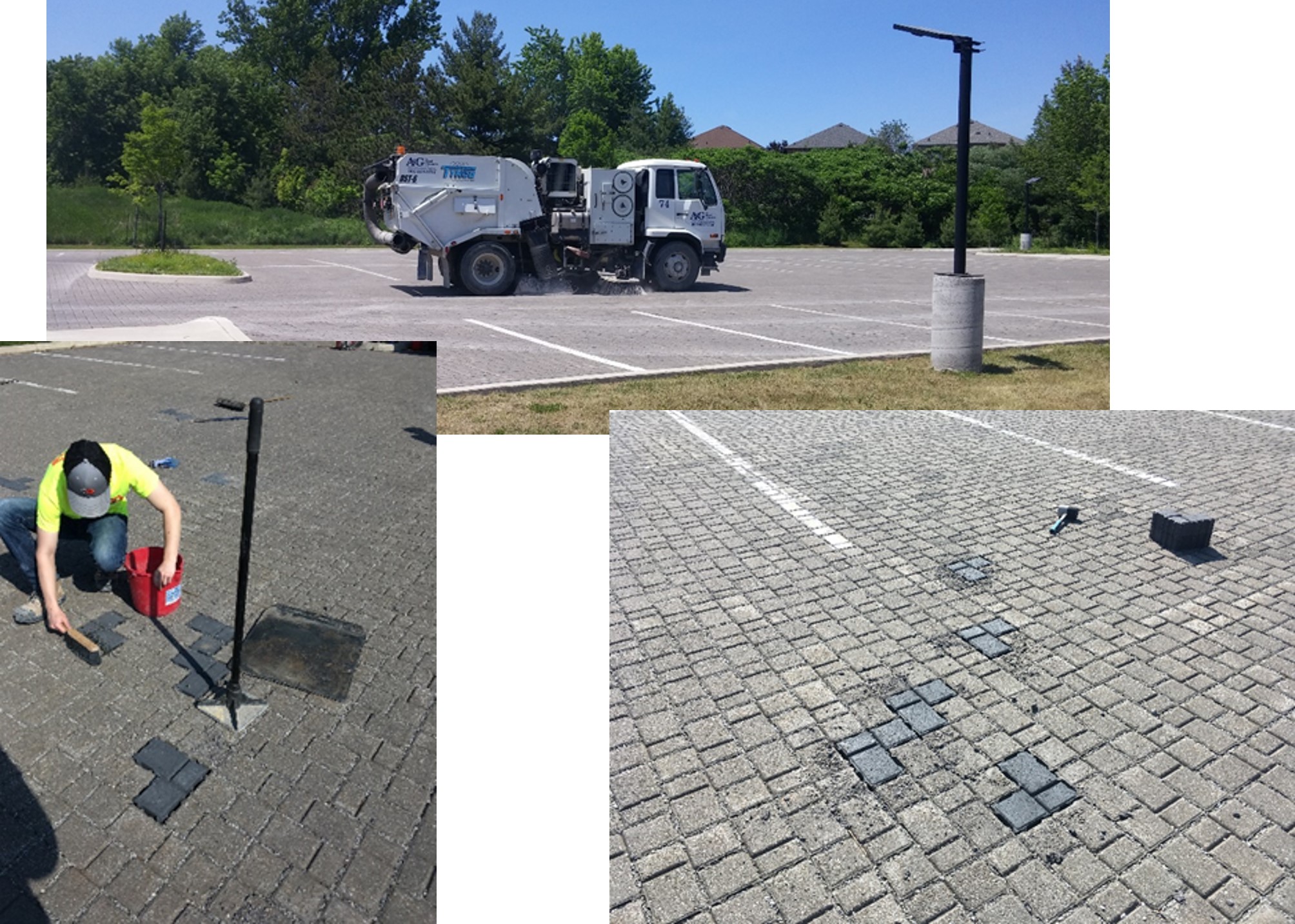
Figure 17. Permeable pavement partial rehabilitation.
6.1.2.3 Damages Due to Business Disruption
In an urban context, there may be damages in the form of business disruptions as a result of construction and/or maintenance. For example, a business may temporarily experience reduced access or reduced parking resulting in lost customers or a business may be required to re-schedule product deliveries causing reduced sales. Understanding the operations of impacted businesses can allow for careful planning to reduce these damages. If possible, construction and maintenance activities should be scheduled in such a way as to not interfere with business operations. When not avoidable, an estimate can be made of the damages that will occur and compensation provided as an allowance.
The following formula can be used to estimate business disruptions due to construction. In practice the business/landowner who has experienced business disruptions should be required to provide documentation to demonstrate a loss of income. Business disruption allowances should not be provided for inconvenience, there must be a loss of revenue.
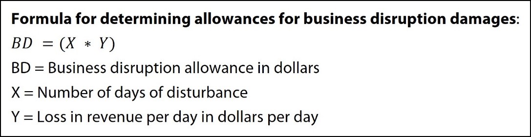
Montreal is the first city in Canada to compensate businesses for construction work business disruption. “Montreal merchants will qualify for up to $30,000 a year in compensation for disruptions caused by city construction projects…merchants will only be eligible for financial compensation after submitting audited financial statements proving they have suffered losses.” [2]
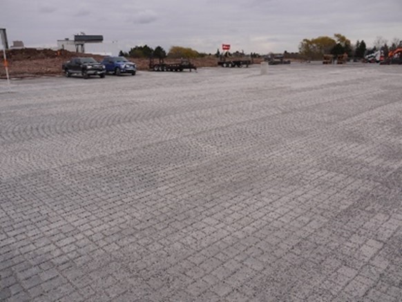
Figure 18. During construction of this permeable paver parking lot in Mississauga, the business had to provide alternate parking and a shuttle bus for employees, thus resulting in business disruptions.
If business disruptions are anticipated to be routine in the future (i.e., for maintenance/rehabilitation) they can be projected using the same formula as maintenance and rehabilitation damage allowances; the cost of business disruption would represent the future value variable. Like damages for maintenance and rehabilitation there are challenges that exist with accurately estimating future costs for business disruptions. As such it is recommended that any business disruptions due to maintenance be levied out as a part of maintenance costs at the time maintenance is completed and the appropriate compensation be provided to the landowner.
Business disruptions can affect industrial areas, commercial and institutional areas. Table 5 provides a list of disruption types that may cause a loss of income.
Table 5. Types of business disruptions that can occur due to construction, maintnenance and rehabilitation work.
| Loss of walk-up customers | Customer Parking | Employee Parking | Deliveries – incoming and outgoing | Temp. loss of outdoor storage | Temp. loss of access to storage facilities | Noise disrup-tion | |
| Industry Type | |||||||
| Trucking terminal | X | X | X | X | |||
| Warehouse | X | X | X | X | |||
| Light industrial | X | X | X | X | X | ||
| Heavy industrial | X | X | X | X | X | ||
| Commercial, institutional or multi-residential zoning type: | |||||||
| Small Strip Mall | X | X | X | X | |||
| Box Mall | X | X | X | X | X | ||
| Restaurant | X | X | X | X | X | ||
| Automotive businesses | X | X | X | ||||
| Office space | X | X | X | ||||
| Multi-residential (condos, apartment buildings) | X | X | X | ||||
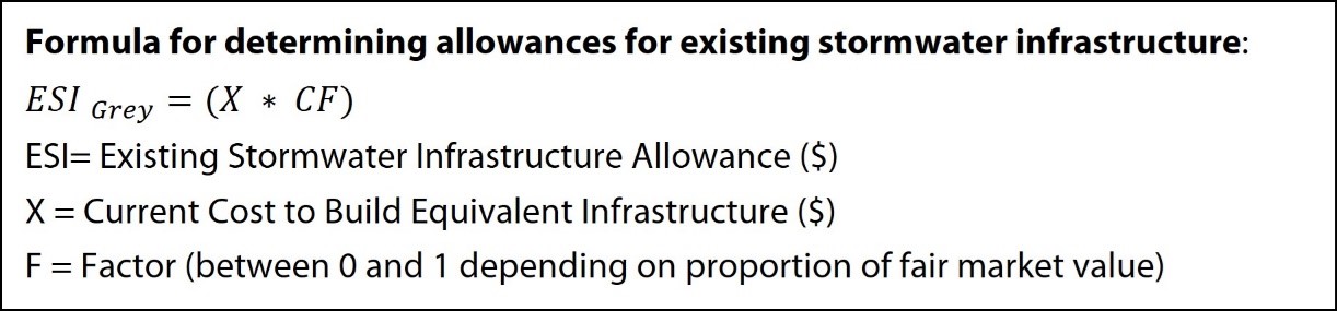
6.1.3 Allowances for Existing Stormwater Infrastructure (Section 31)
Many properties already have existing grey infrastructure drainage systems in place. These features typically include conveyance systems made up of manholes, catch basins, pipes, etc. If these drainage systems and features provide a function and value to the proposed project design, an allowance is necessary to bring them under the easement.
To calculate the value of these features, determine the current cost of equivalent components. The condition, age and capacity of the existing drain should then be evaluated, and the amount of the allowance reduced by an appropriate factor accordingly (Dries, 1998). Capacity can be assessed if it is known which design storm the storm sewers surcharge at; capacity applies to pipes but does not apply to manholes and catchbasins. If an existing pipe is significantly undersized, and thus needs to be replaced, an allowance should not be given for the existing pipe.
Inspections may be required to determine the age, condition and capacity of existing drains. Consider the following methods:
- CCTV inspection.
- Securing designs for the infrastructure in question.
- Simple visual inspection.
- Modelling.
Table 6 contains criteria to consider for developing a factor for determining an accurate value of existing infrastructure. If multiple existing infrastructure criteria are desired, they may be weighted to determine a single factor for reducing full market value to partial market value (it is also possible and may make sense to use different criteria for catchbasins). For existing swales that are incorporated into the drainage works, associated pipes, catchbasins and manholes can be calculated following the method provided above. A partial land allowance for the swale area can be provided to compensate the landowner for easement purposes.
Table 6. Criteria to consider for assigning for partial market value to existing infrastructure.
| Existing Infrastructure Criteria | Details | Suggested Proportions |
| Age | Assign a higher proportion of market value for newer infrastructure. Decrease proportion as needed for older infrastructure. | 0 to 1 |
| Condition | Assign a higher proportion of market value for infrastructure that is in good condition. Decrease proportion as needed for infrastructure in poor condition. | 0 to 1 |
| Capacity | Surcharge at 2-year storm | 0.2 |
| Surcharge at 5-year storm | 0.5 | |
| Surcharge at 10-year storm | 0.8 |
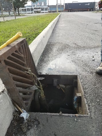
Figure 19. Catch basin.
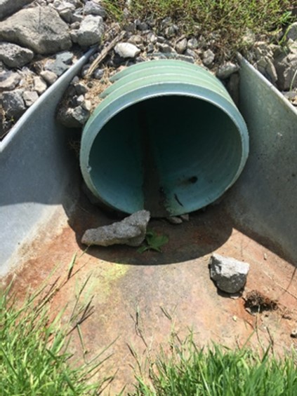
Figure 20. Existing pipe.
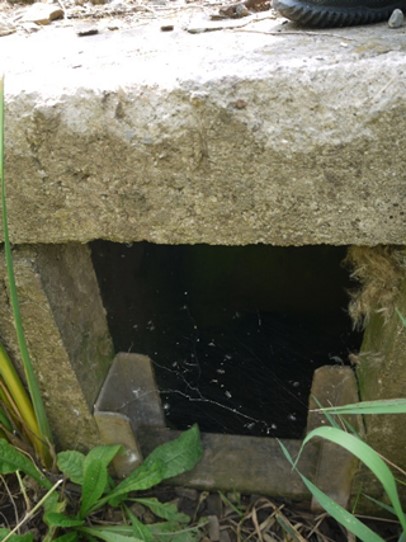
Figure 21. Control structure with stop logs (dam).
6.1.3.1 Allowances for Existing LID
Some landowners will have existing LID, such as bioretention areas or permeable pavement, that are designed to a desired standard. The works on their properties should be given an allowance for the cost to construct them if they provide a function and value to the proposed project design. This allowance should be in addition to the partial land values associated with such features, which are discussed in section 7.1.1.2. To calculate this allowance, follow the same method given for existing grey infrastructure above. When determining the condition factor, the capacity of the LID for stormwater management (peak flow control, reduce reduction and water quality control) should be considered. If existing stormwater infrastructure such as pipes and catch basins are used to convey water from existing LID, they can be accounted for in the existing stormwater infrastructure calculations, as outlined above.
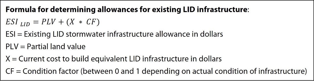
Figure 22. A bioretention facility at Portico Church in Mississauga.
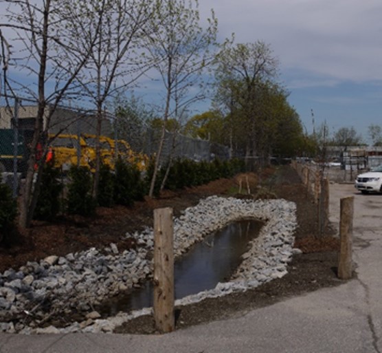
Figure 23. Swales/Sediment Traps.
6.1.4 Allowances for Existing Natural Assets
Landowners should be given an allowance where natural features exist if their function is similar to an LID feature and they are incorporated into the proposed project design. If an allowance is given, then the natural feature is regarded as part of the drain and is protected in the future. The allowance amount for a natural feature should take into consideration the following: any amounts invested by the landowner to install the natural feature, the cost to build a functionally equivalent LID feature, land value, existing encumberances (e.g., regulated floodplain, etc.). If it can be demonstrated by the landowner that they made an investment into the land to add the natural asset (i.e., they planted trees) then additional compensation can be given above and beyond the partial land value.
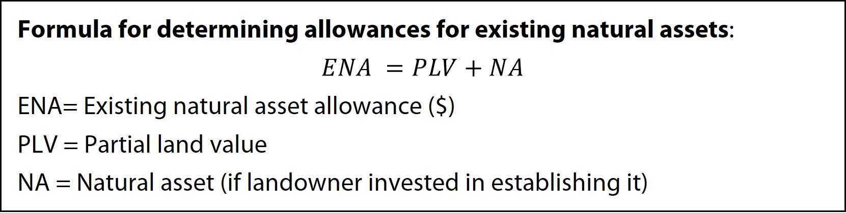
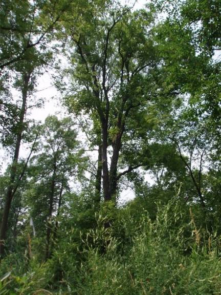
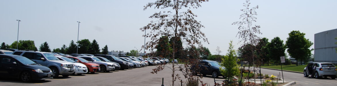
Figure 24. Urban forest cover in the study area.
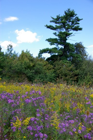
Figure 25. Meadow on a Mississauga property.
Figure 26. Pocket wetland in an urban area.
6.1.5 Allowances for Insufficient Outlet (Section 32)
An allowance for insufficient outlet is required if discharge from the drainage works is likely to cause damage or injury to receiving lands. In an urban context, and for this project the downstream receiving conveyance features have adequate capacity (see Sufficient Outlet Discussion in section 6.2, therefore no allowances for insufficient outlet are included in this report.
6.1.6 Allowances for Loss of Access (Section 33)
In an urban context, loss of access due to the construction of the drainage works in a manner that severs the property is unlikely to occur. The cost of land is high in urban areas thus allowing for loss of access would be too costly.
6.1.7 Allowance Splits
Since costs and assessments were computed separately for each aspect of system (conveyance, water quality and major system flood control), the allowances were also computed separately. To account for the differing use of the infrastructure by the different systems, the following table illustrates the splits used in the report.
Table 7. Percentage splits for infrastructure use by conveyance system, water quality and flood control.
| LID type | Local Conveyance | Water quality / LID | Major system |
| Online chambers | 20% | 40% | 40% |
| Offline chambers | – | 50% | 50% |
| Enhanced swales | 50% | 50% | – |
6.1.8 Summary of Allowances
Allowances were determined on a per property basis for each scenario and are provided in Appendix A2 (scenario 2), Appendix B2 (scenario 3) and Appendix C2 (scenario 4).
A summary of the allowances made per property for each scenario follows in Table 8.
Table 8. Summary of Allowances by scenario per property.
| Roll No. | Owner | Scenario 2 ($) | Scenario 3 ($) | Scenario 4 ($) |
| 21-05-020-XXXX | Property 1 | – | – | – |
| 21-05-020-XXXX | Property 2 | – | – | – |
| 21-05-020-XXXX | Property 3 | – | – | – |
| 21-05-020-XXXX | Property 4 | – | – | – |
| 21-05-020-XXXX | Property 5 | 322,800 | 885,200 | – |
| 21-05-020-XXXX | Property 6 | 285,900 | 783,200 | – |
| 21-05-020-XXXX | Property 7 | 7,200 | 108,400 | – |
| 21-05-020-XXXX | Property 8 | – | 91,600 | – |
| 21-05-020-XXXX | Property 9 | 411,600 | 525,300 | – |
| 21-05-020-XXXX | Property 10 | 483,400 | 527,400 | – |
| 21-05-020-XXXX | Property 11 | 304,300 | 350,600 | – |
| 21-05-020-XXXX | Property 12 | – | 12,500 | – |
| 21-05-020-XXXX | Property 13 | – | 26,400 | – |
| 21-05-020-XXXX | Property 14 | – | – | 6,623,500 |
| CNR | Property 15 | – | 132,000 | – |
| Total Allowances: | 1,815,200 | 3,442,600 | 6,623,500 | |
6.2 Construction Costs
The estimated cost for labour, equipment and materials to construct the proposed drain is provided in Appendix A1 (scenario 2), Appendix B1 (scenario 3) and Appendix C1 (scenario 4).
For scenarios 2 and 3, the construction cost estimate is from the STEP LID Life-Cycle Costing Tool (Version 3) [1], which uses recent costs for comparable works. Contingency amounts are included to cover additional work that may be required due to unforeseen field conditions, minor alterations to the project and rising construction costs.
Local/municipal procurement policies will dictate the applicable quotation/tendering process. Since the majority of the work is funded by private landowners, consideration should be given at the time of construction to phasing or bundling the work in way that minimizes the burden to private landowners to pay the “overhead” costs associated with larger, more complex construction firms and projects. Where multiple construction specialties are included in a single Drainage Act report, it may be advantageous to construct the work using multiple contractors.
If the contract price is more than 33 per cent over the engineer’s estimate, section 59 of the act requires a decision by council, with input from the petitioners / assessed landowners to determine if the project should proceed.
6.3 Engineering
Engineering costs include survey, design, landowner consultations, subconsultants as applicable (e.g., geotechnical, environmental, archeological reports) and preparation of the cost estimates, assessment schedules and this report. The cost for report preparation is usually not altered at the conclusion of a project unless the report is referred back or the report is appealed to the Drainage Tribunal which would result in additional costs.
Meetings for consideration of the report by council and the Court of Revision are also included in the estimated cost for engineering services. Final cost will be based on the actual time required for meetings.
Construction phase services typically provided by the engineer include: preparing tender documents, review of tenders, award recommendation, assisting with permits, attending pre-construction meeting, construction inspection, contractor payments, final inspection, post construction follow-up and final cost analysis. As applicable, the estimate for construction phase services also includes amounts for subconsultant services that will be required during construction.
The estimate shown for construction phase services is based on past experience and assumes good construction conditions and a contractor who completes the construction in an efficient manner. The final cost for the construction phase services will vary as per the actual time spent during and following drain construction.
6.4 Section 73 Costs
Sections 73(2) and 73(3) of the act direct that the cost of services provided by municipal staff and council to carry out the act process shall not form part of the final cost of the drain. However, section 73(1) outlines that the following costs incurred by the municipality can be included in the cost of the drain: “cost of any application, reference or appeal and the cost of temporary financing.”
The estimate of section 73 costs is included to cover the above referenced items from section 73(1) and primarily provides for interest charges on financing the project until it is completed. This cost estimate may not be adequate to cover legal or engineering costs incurred by or assessed to the municipality should the project be appealed beyond the Court of Revision though such costs will form part of the final drain cost.
6.5 Cost Comparison
The total life-cycle costs, minimizing disruption to business operations and landowner input were considered to determine the optimal solutions. Maintenance costs were also considered in the design and recommendations. The following table presents the annualized operational and maintenance cost for scenarios 2, 3 and 4 over a 50-year life-cycle.
Table 9. Operation and maintenance costs.
| BRANCH | Area (ha) | Scenario 2 | Scenario 3 | Scenario 4 |
| D | 5.5 | 4,800 | 5,500 | 12,300 |
| E | 1.3 | 2,200 | 2,900 | 2,900 |
| F | 3.1 | 2,000 | 3,300 | 6,900 |
| G & H | 2.6 | 1,900 | 2,900 | 5,800 |
| I | 4.7 | 2,400 | 3,900 | 10,500 |
| Total | 13,300 | 18,500 | 38,400 |
Scenario 2 provides the lowest annual operation and maintenance costs.
The following table summarizes the total costs of the scenarios.
Table 10. Total cost by scenario.
| Cost Category | Scenario 2 | Scenario 3 | Scenario 4 |
| Allowances | 1,815,000.00 | 3,443,000.00 | 6,623,500.00 |
| Construction | 2,345,000.00 | 3,353,.00 | 767,200.00 |
| Engineering | 477,000.00 | 571,000.00 | 115,000.00 |
| Section 73 | 54,000.00 | 74,000.00 | 0 |
| Initial costs | 4,691,000.00 | 7,441,000.00 | 7,507,700.00 |
| O&M Cost (50-year life- cycle) | 417,000.00 | 571,000.00 | 1,211,200.00 |
| Total life-cycle costs | 5,108,000.00 | 8,012,000.00 | 8,660,100.00 |
Based on the estimated total life-cycle costs, scenario 2 is the least costly while maximizing the stormwater management credits. Scenario 4 is the most costly, with the largest loss of usable land. Scenario 3, while comparable in cost to scenario 4 has the advantage that the landowner would receive stormwater management credits with numerous co-benefits to the natural environment and surrounding area.
7 Results, Discussion and Recommendations
7.1 Modelling Scenarios
A PCSWMM model of the site was created by CHI Consulting Engineers. Five scenarios were modelled; pre-development conditions, the existing conditions, scenarios 2, 3 and 4. The models were used to determine the credits, the capacity of existing system, to size a local conveyance system and flow reduction of scenario 3.
As part of the design process, CVC staff met with landowners to review drainage mapping and model results. Model results related to flooding locations/depths were generally consistent with landowner observations (see “CVC Southdown District Aggregated and Communal LID Practices Stormwater Retrofit Modelling” Report).
7.1.1 Scenario 1 – Existing Conditions
Scenario 1 is intended to determine the existing conditions. After the model was completed, field checks were conducted to verify the model results. Flooding was observed in the same areas identified by the model. The existing drainage system is a mixture of underground pipes and structures, swales and ditches. Some of the system around the GO stations appear to be sized for the 5-year return storm but, most of the systems on private lands appear to be sized for under the 2-year return storm with no consistent design standard.
Table 11. Existing conditions infrastructure.
| Branch | Type | Length | Return Storm | Comments |
| D | Piped and swale | 471m piped, 270m swale | Less than 2-year | City yard, mixture of surface swale and piped system, multiple properties |
| E | Piped and swale | 70m piped, 189m swale | Less than 2-year | Built on property line, no design drawings for systems |
| F | Piped and ditch | 149m piped, 190 ditch | Less than 2-year | Design drawings exist for part of this system |
| G | Piped | 132m piped | Less than 2-year | No design drawings for systems |
| H | Piped | 246m piped | Less than 2-year | No design drawings for systems |
7.1.2 Scenario 2 – Maximum Credit
The maximum credit design uses LID practices on private property to gain the maximum amount of stormwater credit available to landowners at the lowest cost. Successful applicants can receive a maximum of 50 per cent credit on their annual stormwater charge for installing at-source LID practices and for developing property-specific pollution prevention plans (Table 8 in “Communal Low Impact Development Approach to Manage Stormwater” report).
Several LID types were investigated to meet the intent of the scenario, to maximize the stormwater credit for the lowest cost. The design of the max credit scenario went through several iterations and it was found to be most cost effective to use a combination of infiltration chambers, enhanced grass swales, oil and grit separators and infiltration trenches to achieve the 50 per cent stormwater credit.
7.1.3 Scenario 3 – One Water
The “one water” design considered reducing stormwater inflow/infiltration into the sanitary sewers and water conservation. The “one water” approach recognizes all water types as resources and part of one integrated system. It considers drinking water, wastewater and stormwater together at a watershed scale. There can be water resources benefits if stormwater is managed holistically considering other water systems instead of focusing on stormwater individually.
The “one water” design aimed to optimize environmental benefits, going beyond the maximum credit criteria despite the city’s credit ceiling at a rebate of 50 per cent. The extra benefits were achieved by converting the enhanced grass swales that were part of scenario 2 to bioswales in scenario 3. The infiltration trenches under storage chambers in scenario 2 were also adjusted in scenario 3 so that additional volume reduction could be achieved. In addition to stormwater, scenario 3 also considered other co-benefits of LID.
In the study, the stormwater design was optimized to include urban forest areas. Tree canopy can help mitigate urban heat by providing shade and by allowing for evapotranspiration to occur. Trees also help with stormwater management as the canopy can capture rainwater and prevent runoff. Existing lawn and treed areas were selected as good options for urban forests. Also, the enhanced grass swales that were a part of the conceptual design were proposed to become bioretention facilities that include trees.
7.1.4 Scenario 4 – End of Pipe
Scenario 4 considers end-of-pipe stormwater management solutions for the 13 property study area. An analysis of the major and minor systems has been used to establish the required volume of stormwater runoff control to prescribed targets (in this case the aggregated outlets of the two primary drainage areas, as discussed further in section 2.2.2). The various SWM facilities considered for this study area (referenced as Ponds 1, Pond 2) were sized according to the guidance offered in the 2003 MOE, Stormwater Management Planning and Design Manual. The costs were estimated using the Sustainable Technologies Evaluation Program’s (STEP) Low Impact Development Life-Cycle Costing Tool (LCCT). The design criteria included:
- Peak Flow Control
- Provide control of the 100-year storm event.
- Water Quality Storage Volume
- Enhanced protection (80 per cent TSS removal).
- Other Design Criteria
- Drainage area greater than 10 hectares for the end-of-pipe facilities.
- Extended detention storage requirement equals 40 cubic metres per hectare.
- Forebay volume equals 20 per cent of permanent pool.
- Pond and forebay length to width ratio of 4:1.
- Wet pond permanent pool depth equals 1.5 metres.
- Active storage depth equals 1.5 metres.
- Freeboard equals 0.3 metres.
- 10 meter buffer zone on all sides of the pond for maintenance access.
7.2 Discussion
Each scenario was evaluated based on overall cost, maximizing stormwater credits for landowners, resolving existing flooding issues, minimizing the impact of construction on business operations, preserving land usability and minimizing operation and maintenance costs.
Scenario 1 is not a viable option as the current property owners pay the full stormwater utility fee and existing flooding problems persist.
Scenario 2 is the recommended option; it maximizes the credits from the stormwater management fee with minimum loss of land and disruption to business operations.
Scenario 3 has the most environmental benefits and is the second most expensive. Features from this scenario could be installed on a per-property basis if requested by landowners.
Scenario 4 is the most expensive option, does not resolve any local flooding problems, only treats water leaving the site through existing infrastructure and requires a significant amount of land for construction of the pond(s).
7.3 Recommendations
A summary of the scenario 2 proposed works is given below in Table 12.
Table 12. Summary of scenario 2 proposed works.
| Branch | Catchment Area (hectares) | Total Length of Subsurface Conveyance to Construct or Incorporate (metres) | Total Length of Surface Conveyance to Construct or Incorporate (metres) | Other Features |
| D | 5.5 | 346 | 441 | Storm Chambers “D-1” and “D-2” |
| E | 1..3 | 132 | 75 | Storm Chamber “E-1” |
| F | 3.1 | 149 | 219 | Storm Chambers “F-1” and “F-2” |
| G/H | 2.6 | 379 | 0 | Storm Chamber “H-1” |
| I | 4.7 | 119 | 356 | Storm Chamber “I-1” |
Details for the recommended work under scenario 2 are presented on the drawings in Appendix D. Specifications for construction and maintenance of the drain are not included with this example report, but are required for all formal reports under the Drainage Act.
8 Assessing Drain Cost
The Drainage Act requires that the total estimated cost be assessed to the affected lands and roads under the categories of benefit (Section 22), outlet liability (section 23), injuring liability (section 23), special benefit (section 24) and increased cost (section 26). On this project assessment for benefit, special benefit (scenario 3 only) and outlet liability are used.
8.1 General Assessment Methodology
Key components/principles of the assessment methodology include:
- Separating the drainage works into intervals (sub-sections) based on service area to ensure lands are only assessed for the portions of the drainage works they use.
- For this urbanized watershed, the drainage works for each interval were further discretized into three sub-components, based on the type of service provided: existing infrastructure for minor event conveyance, proposed water quality infrastructure (LID), and major event conveyance features.
- For each sub-component of each interval, the contributing areas were identified and classified based on runoff characteristics.
- For each sub-component of each interval, benefit assessments were determined for the affected properties.
- The sum of all benefit assessments for each interval was subtracted from the total interval cost and the remainder assessed as outlet liability on an area basis to the contributing lands and roads in the interval.
- Finally, the net assessment for each parcel was determined by combining all benefit and outlet assessments and then subtracting the total allowances due to the property.
- Section 9.5 below provides a detailed example of the assessment methodology for Branch F under scenario 2.
8.2 Benefit Assessments (Sections 22 and 24)
In accordance with the Drainage Act, section 22 benefits were determined based on the estimated value provided to the property by the works and are not proportional to the watershed area. Section 9.5 in this report illustrates how benefits were determined for branch F. The following table shows the benefit outlet splits used to determine the assessments in this report. The benefit reflects the benefit that the different conveyance systems receive.
Table 13. Benefit and outlet assessment proportions.
| Branch | Benefit / Outlet | ||
| Local Conveyance | Water quality/LID | Major system | |
| D | 25% / 75% | 95% / 5% | 95% / 5% |
| E | 50% / 50% | 80% / 20% | 90% / 10% |
| F (1-4) | 50% / 50% | 80% / 20% | 90% / 10% |
| F (5-8) | 25% / 75% | 80% / 20% | 90% / 10% |
| G/H | 90% / 10% | 95% / 5% | 95% / 5% |
| I | 70% / 30% | 80% / 20% | 90% / 10% |
Section 24 special benefits may be assessed to lands where additional work or features are included in construction that are not necessary for the function of the drain. Special benefit examples generally include aesthetic enhancements, upgraded system capacity which is above the design standard used for the project or any other work requested by an affected landowner which, as defined in section 1 of the Drainage Act has “no effect on the functioning of the drainage works.” Special benefits are generally assessed directly to the requestor and may be based on actual costs.
8.3 Outlet Liability Assessments (Section 23)
Section 23(3) of the Drainage Act states that outlet liability assessment is to be based on the volume and rate of flow of the water artificially caused to flow. Therefore, the lands and roads in the watershed are assessed on a per hectare basis, with adjustments made to recognize the different amount of runoff generated by different land uses. The factors used for outlet liability calculations are presented below in Table 14.
Table 14. Runoff adjustment factors for outlet liability calculations.
| Land Cover Type | Runoff Coefficient | Minor System 2 year | 10 year | 25 year | 50 year | Major System 100 year |
| 1 | 1.1 | 1.2 | 1.25 | |||
| Building, pavement, asphalt | 0.9 | 0.9 | 0.9 | 1.0 | 1.1 | 1.1 |
| Gravel 1 | 0.9 | 0.9 | 0.9 | 1.0 | 1.1 | 1.1 |
| Lawn/Landscaped/Treed | 0.4 | 0.4 | 0.40 | 0.44 | 0.48 | 0.50 |
| Split Drainage (minor) 2 | 0 | 0.0 | ||||
| Split Drainage (major) 3 | 1.0 | 1.0 | ||||
| Existing LID 4 | 0.1 | 0.1 | 0.10 | 0.11 | 0.12 | 0.13 |
Notes:
- Gravel is assigned a runoff coefficient of 0.9 due to compacted nature and considered equivalent to impervious surface.
- Split drainage (minor) – Minor drainage system is diverted away from branch.
- Split drainage (major) – Major drainage system spills into branch.
- Existing LID – Designed as part of the minor system (conveyance, water quality, erosion)
- City of Mississauga Section 8 Stormwater Drainage Design Requirements (PDF, 1.2 MB) [3]
8.4 Increased Cost (Special) Assessments (Section 26)
Section 26 of the Drainage Act directs that any increased cost due to a public utility (utility) or road authority (road) shall be paid for by that utility or road. This assessment is commonly referred to as a special assessment.
No special assessments have been calculated for this project since no work is anticipated at Royal Windsor Drive. However, if increased costs are incurred during construction due to a public utility or road, the increased construction and/or engineering costs may be assessed as a special assessment to the owner of the public road or utility at the conclusion of the project.
To reduce special assessment amounts, the road authority or utility may elect to construct the drain within their right of way with their contractor.
8.5 Detailed Assessment Example – Branch F, Scenario 2
This section outlines the sequence of steps used to determine branch F assessments.
Overview:
- Branch F is shown on drawings 12 to 15.
- Key components of branch F include:
- Incorporation of 149 metres of 375 millimetre diameter plastic pipe discharging to the storm sewer under Royal Windsor Drive, which is 1,950 millimetre diameter where branch F connects.
- Construction of two new storm chambers (F-1 and F-2)
- Construction of 187 metres of enhanced grass swale
- Ancillary storm manholes/catchbasins, erosion control measures and surface restoration work.
- Branch F is situated along/on parcels designated as P6, P7, P8 and P10.
- Runoff to branch F is from P6, P7, P8 and P10.
Assessment Steps:
- Branch F was divided into 8 intervals, with interval splits at nodes along the drain where additional catchment areas connect to the system.
- For each interval of branch F, the upstream catchment area was measured and characterized based on land use/runoff characteristics. Tables 15-3A, 15-3B and 15-3C present area measurements and area adjustments based on the runoff adjustment factors shown above in Table 14.
- The total cost of branch F was determined:
- Table 15-4 provides the cost of branch F allowances.
- Table 15-5 provides the detailed breakdown of estimated construction, engineering and eligible administrative costs for branch F.
- Table 15-6 presents total cost of branch F on a per interval basis.
- For each interval of branch F, the interval cost was split among the three sub-components: existing minor conveyance features (Table 15-6A), new water quality LID features (Table 15-6B) and major event conveyance (Table 15-6C).
- Tables 15-8A, 15-8B and 15-8C present the benefit ratios which govern the amount of each interval assessed as section 22 benefit assessment. The benefit ratios are generally consistent with industry practice and further justified on a per-property basis under subsequent calculation steps.
- For each sub-component of branch F, benefit assessments were computed separately on a per-property basis:
- Table 15-9A – Benefit assessments for existing minor conveyance features are proportional to the length of the conveyance used by each property.
- Table 15-9B – Benefit assessments for new water quality features were assessed to the City of Mississauga as cut-off benefit, since new LID features improve stormwater quantity and stormwater quality for downstream city infrastructure.
- Table 15-9C – Benefit assessments for major event conveyance features is shared by the city (due to cut-off benefit of reduced major event flows) and property owners (due to improved protection of property against major event damage).
- Benefit assessments determined in previous steps were inserted in Tables 15-10A, 15-10B and 15-10C, summed on a per-interval basis, and the remaining costs in each interval assessed pro-rata as outlet liability, on a per-parcel basis using the adjusted areas contributing runoff to the drain.
- Branch F gross assessments are summarized for existing minor conveyance features (schedule A1), new water quality LID features (schedule A2) and major event conveyance (schedule A3).
- Branch F net assessments, which reflect out-of-pocket reductions due to allowances, are shown in schedule A4.
- Branch F future maintenance costs are to be assessed with the following schedules: existing minor conveyance features (schedule B1), new water quality LID features (schedule B2) and major event conveyance (schedule B3).
8.6 Assessment Schedule for the Actual Cost Bylaw
After the construction of the drain is certified complete by the engineer, the municipality will determine the actual cost of the drain. Actual assessments will be determined by prorating the actual cost of the drain using the net assessments shown in schedule A4. Schedule A4 illustrates the estimated net assessments after deducting allowances and grants/credits from the total assessments shown in schedule A4. Eligibility for the grant/credits will be confirmed by the municipality at the time the actual cost is levied. Actual cost assessments per schedule A4 will be levied to the owner of the identified parcel at the time the actual cost bylaw is passed.
8.7 Assessment of Future Maintenance
In accordance with section 74 of the Act, the drain shall be maintained by the municipality, and the cost of maintenance shall be assessed to lands and roads upstream of the maintenance location, pro rata with the amounts shown in the future maintenance schedules.
Amounts and/or percentages shown in future maintenance schedules B1, B2 and B3 are not payable at this time; they determine the share of future maintenance costs. The municipality will confirm eligibility for grants (if any) at the time the maintenance cost is levied.
Maintenance schedules are divided into columns to reflect the different drain intervals where maintenance work may be undertaken. These column intervals assist in identifying upstream lands and roads to be assessed for future maintenance.
9 Maintenance
9.1 General Procedures
Section 74 of the act requires the drain, as outlined in this report, to be maintained by the municipality, and the cost of maintenance to be assessed to the upstream lands and roads pro rata with the assessments in schedule B. One hundred per cent of the cost for future maintenance of drainage works within the Royal Windsor Drain right-of-way shall be assessed to the city.
All parties affected by the drain, are encouraged to periodically inspect the drain and report any visible or suspected problems to the municipality.
A right-of-way along the drain and access routes to the drain exist for the municipality to maintain the drain. The right-of-way corridor for the drain shall remain free of obstructions. The cost of removing obstructions at the time the municipality undertakes future maintenance is the responsibility of the owner.
Any landowner making a new connection to the drain shall notify the municipality’s drainage superintendent before making the connection. If the drainage superintendent is not notified, the cost to remedy new connections that obstruct or otherwise damage the drain will be the responsibility of the owner.
If future site alterations are undertaken by landowners which require changes to the drainage works identified in this report, including impacts to major event overflow routes, the landowner is required to contact the municipality so the changes to the drain can be properly authorized via a Drainage Act process subsequent to this report (e.g., a section 78 report to improve the drain or a minor improvement under O. Reg. 500/21, or another Drainage Act process.)
The discharge of anything but clean, unpolluted water into a drain is regulated by other provincial legislation. Any non-compliance will be reported to the appropriate environmental agency.
For each branch and sub-component of the system, this report includes a customized assessment schedule for levying future maintenance costs against the lands and roads who are upstream of the location of the maintenance work.
9.2 Updating Future Maintenance Schedules
To ensure future maintenance assessments are equitable, the assessments provided in this report should be reapportioned under section 65 when severances or amalgamations occur when new lands are connected to the drain or when a land-use change occurs that can be accommodated by the existing drain. If a future land-use change will cause the drain capacity to be exceeded, a report under sections 4 or 78 may be required to provide increased capacity.
10 Report Limitations
While this report satisfies most of the Drainage Act requirements for an engineer’s report, this document is intended for proof-of-concept purposes only. The Drainage Act framework can be applied in urban settings to design, fund and maintain drainage infrastructure on private land. An authoritative engineering report would require proper initiation via landowner petition(s) and council appointment. Drawings provided with this report are not for construction or permitting purposes and would require further detailed design prior to implementation.
Although the recommended works would improve drainage, the current stormwater credit program suggests private landowners would face a 10-year or greater payback period, based on the Drainage Act assessment methodology used in this report. Further credits or external grants and funding sources would reduce this payback period and encourage more private LID features in a watershed.
11 Privacy of Lands
Although a municipal drain is situated on the property of various landowners, one landowner may not enter another landowner’s property by means of the drain. Persons authorized to enter private lands to carry out duties authorized under the act include: engineers (or their assistants), contractors (or their assistants) and the appointed drainage superintendents (or their assistants).
12 Bylaw
This report including the drawings and specifications, assessment schedules and appendices, when adopted by bylaw in accordance with the act, provides the basis for construction and maintenance of the drain.
13 References
[1] https://sustainabletechnologies.ca/lid-lcct/
[2] https://www.cbc.ca/news/canada/montreal/montreal-construction-plan-1.4704081
[3] http://www7.mississauga.ca/Departments/Marketing/documents/tw/FINAL-Section-8-Storm-Drainage-Design-Requirements-Jan2020.pdf
14 Publication Information
This guidance document was prepared by Credit Valley Conservation through the Sustainable Technologies Evaluation Program and K. Smart Associates Limited.
Citation: Credit Valley Conservation (CVC) and K. Smart Associates Limited. 2023. Drainage Act Report, Southdown Drain. Credit Valley Conservation, Mississauga, Ontario.
Documents prepared by the Sustainable Technologies Evaluation Program (STEP) are available at www.sustainabletechnologies.ca. For more information about this or other STEP publications, please contact:
Phil James P.Eng.
Senior Manager, Integrated Water Management
Credit Valley Conservation Authority
1255 Old Derry Road
Mississauga, Ontario
E-mail phil.james@cvc.ca
Kyle Vander Linden
Senior Advisor, Guidance, Policy and Strategic Partnerships, Integrated Water Management
Credit Valley Conservation
1255 Old Derry Road
Mississauga, Ontario
E-mail kyle.vanderlinden@cvc.ca
15 STEP
The water component of the Sustainable Technologies Evaluation Program (STEP) is a partnership between Toronto and Region Conservation Authority (TRCA), Credit Valley Conservation and Lake Simcoe Region Conservation Authority. STEP supports broader implementation of sustainable technologies and practices within a Canadian context by:
- Carrying out research, monitoring and evaluation of clean water and low carbon technologies;
- Assessing technology implementation barriers and opportunities;
- Developing supporting tools, guidelines and policies;
- Delivering education and training programs;
- Advocating for effective sustainable technologies; and
- Collaborating with academic and industry partners through our Living Labs and other initiatives.
Technologies evaluated under STEP are not limited to physical devices or products; they may also include preventative measures, implementation protocols, alternative urban site designs, and other innovative practices that help create more sustainable and livable communities.
16 Acknowledgements
Funding support for this document was generously provided by:
- Federation of Canadian Municipalities
- City of Mississauga
- Region of Peel
We would also like to thank everyone who contributed to this guide by providing data, technical review, and expert advice on behalf of the following organizations:
- John Kuntze (K. Smart Associates Ltd.)
- Neal Morris (K. Smart Associates Ltd.)
- Kay Palmer (K. Smart Associates Ltd.)
- Alex Paisley (K. Smart Associates Ltd.)
- Marcia Wilson (K. Smart Associates Ltd.)
17 Notice
While support was received from the above noted individuals and agencies to prepare this document, such support does not indicate their endorsement of its contents. Although every reasonable effort has been made to ensure the integrity of the contents of this document, the supporting individuals and agencies do not make any warranty or representation, expressed or implied, with respect to the accuracy or completeness of the information contained herein. Mention of trade names or commercial products does not constitute endorsement or recommendation of those products. The purpose of this communication is to provide general information of a legal nature. It does not contain a full analysis of the law nor does it constitute an opinion on the points of law discussed.